On this page
ADs that cite it · 1
Newest first, with the revision each names, as OpenAirDocs read it from the AD’s text: check it against the AD.
Also cited in 1 proposed AD.
Text · 38Partly OCR
Some pages are OCR from a scan. OCR can misread letters and numbers. © Mitsubishi. Filed by the FAA in regulations.gov docket FAA-2014-0108, the docket of AD 2015-01-02. Not covered by OpenAirDocs’ CC0 dedication.
Query with SQL
duckdb -csv -c "SELECT p.page, p.text_source, p.text, f.rights_holder, f.license
  FROM 'https://openairdocs.org/data/latest/service_document_file_page.parquet' p JOIN 'https://openairdocs.org/data/latest/service_document_file.parquet' f USING (file_sha256)
  WHERE p.file_sha256 = 'f3bb08d5bef0ae7b8f51db7b4a11e6e152b9c0c0b0e4ddaaf90b443feec5e07d'
  ORDER BY p.page"
Prints the whole list as CSV. It reads the release’s Parquet files over HTTPS, so there’s nothing to download first. Install DuckDB to run it.
SELECT p.page, p.text_source, p.text, f.rights_holder, f.license
FROM 'https://openairdocs.org/data/latest/service_document_file_page.parquet' p JOIN 'https://openairdocs.org/data/latest/service_document_file.parquet' f USING (file_sha256)
WHERE p.file_sha256 = 'f3bb08d5bef0ae7b8f51db7b4a11e6e152b9c0c0b0e4ddaaf90b443feec5e07d'
ORDER BY p.page
Run it at the DuckDB prompt, or in any tool that reads Parquet over HTTPS. More ways to query the release are on Use the data.
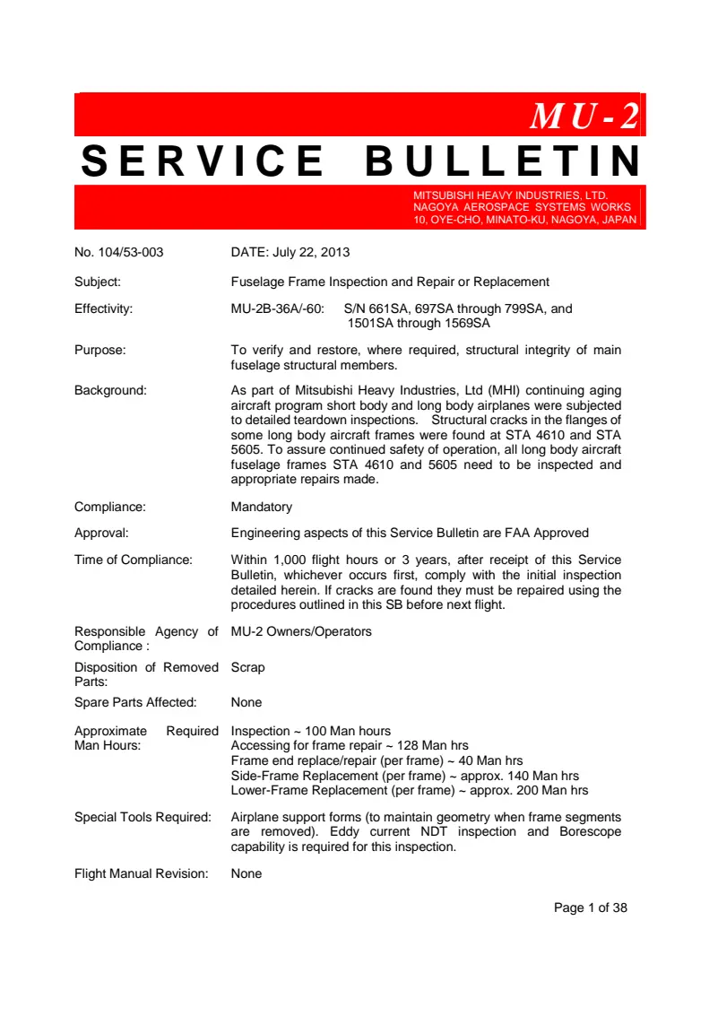
M U - 2
S E R V I C E B U L L E T I N MITSUBISHI HEAVY INDUSTRIES, LTD.
NAGOYA AEROSPACE SYSTEMS WORKS 10, OYE-CHO, MINATO-KU, NAGOYA, JAPAN
Page 1 of 38 No. 104/53-003 DATE: July 22, 2013
Subject: Fuselage Frame Inspection and Repair or Re placement Effectivity: MU-2B-36A/-60: S/N 661SA, 697SA through 799SA, and 1501SA through 1569SA Purpose: To verify and restore, where required, str uctural integrity of main fuselage structural members.
Background: As part of Mitsubishi Heavy Industries, Ltd (MHI) continuing aging aircraft program short body and long body airplanes were subjected to detailed teardown inspections. Structural crack s in the flanges of some long body aircraft frames were found at STA 46 10 and STA 5605. To assure continued safety of operation, all long body aircraft fuselage frames STA 4610 and 5605 need to be inspec ted and appropriate repairs made.
Compliance: Mandatory Approval: Engineering aspects of this Service Bulle tin are FAA Approved Time of Compliance: Within 1,000 flight hours or 3 years, after receipt of this Service Bulletin, whichever occurs first, comply with the i nitial inspection detailed herein. If cracks are found they must be r epaired using the procedures outlined in this SB before next flight.
Responsible Agency of Compliance :
MU-2 Owners/Operators Disposition of Removed Parts:
Scrap Spare Parts Affected: None Approximate Required Man Hours:
Inspection ~ 100 Man hours Accessing for frame repair ~ 128 Man hrs Frame end replace/repair (per frame) ~ 40 Man hrs Side-Frame Replacement (per frame) ~ approx. 140 Man hrs Lower-Frame Replacement (per frame) ~ approx. 200 Man hrs Special Tools Required: Airplane support forms (to maintain geometry when frame segments are removed). Eddy current NDT inspection and Bores cope capability is required for this inspection.
Flight Manual Revision: None
MU-2 Service Bulletin No. 104/53-003 DATE: July 22, 2013
Page 2 of 38 Table of Contents
1.0 APPLICABLE REFERENCE MANUALS3
2.0 GENERAL NOTES3
3.0 FRAME INSPECTION5
3.1 PREPARATION FOR INSPECTION5
3.2 DETAILED INSPECTIONS6
3.3 RESTORATION7
4.0. GENERAL PREPARATION FOR REPAIR/REPLACEMENT7
5.0 LOWER FRAME SEGMENT-END REPLACING REPAIR9
5.1 STA 4610 FRAME SEGMENT-END REPLACING REPAIR (L/H OR R/H)10
5.2 STA 5605 FRAME SEGMENT-END REPLACING REPAIR (L/H OR R/H)11
6.0 REPLACEMENT OF SIDE-FRAME SEGMENTS (STA 4610 or STA 5605)13
6.1 REMOVAL OF LEFT SIDE-FRAME SEGMENT (STA 5605)13
6.2 REMOVAL OF RIGHT SIDE-FRAME SEGMENT (STA 5605)15
6.3 INSTALLATION OF REPLACEMENT SIDE-FRAME SEGMENT16
7.0 REPLACEMENT OF LOWER-FRAME SEGMENT
(CENTER SEGMENT AT STA 4610 OR STA 5605)17
7.1 PREPARATIONS18
7.2 REMOVAL OF LOWER-FRAME SEGMENT STA 461019
7.3 REMOVAL OF LOWER-FRAME SEGMENT STA 560519
7.4 INSTALLATION OF LOWER-FRAME SEGMENTS19
8.0 RESTORATION20
9.0 LOGBOOK ENTRY20
10.0 COMPLETION21
11.0 PARTS AND MATERIAL REQUIRED & SYMMETRICAL MEASUREMENTS ….. 22
12.0 FIGURES28
MU-2 Service Bulletin No. 104/53-003 DATE: July 22, 2013
Page 3 of 38
1.0 APPLICABLE REFERENCE MANUALS Refer to the applicable MU-2 Maintenance Manual, Illustrated Parts Catalog, and Structural Repair Manual.
2.0 GENERAL NOTES
a. Repair Kit’s and/or Replacement frames may be pu rchased through Mitsubishi Heavy Industries America, Inc. (MHIA) Service Center Network.
b. Unless there is an MHI, MHIA or FAA approved rep air, the affected frame sections must be replaced.
c. Properly identify all components removed or disr upted.
d. Restoration of disrupted systems, including rigg ing/operational tests, should be accomplished in accordance with applicable Maintenance Manuals.
e. Frames with surface corrosion should be repaired utilizing repairs outlined in the Structural Repair Manual (SRM).
f. If additional information is needed, contact MHI A Engineering.
This Service Bulletin covers three basic steps in the process of assuring the frame structure at STA 4610 and STA 5605 is sound. The three steps ar e:
1) Detail visual inspection of the frame flanges [Paragraph 3],
2) Repair or Replacement of damaged frame segments [Paragraph 4 thru 7] and
3) Restoration of the Aircraft & Completion [Paragraph 8, 9 & 10].
Any cracking in the frame flanges at STA 4610 and STA 5605 is classified as “Damage Repairable by Replacement” in Section 1, Paragraph 6.5 of the SRM. That is, if the cracking is limited to the ends of the large lower frame segment it is simpler to replace only the damaged ends. If cracking extends over several inches and into the center section of the lower frame then the entire frame segment should be replaced. In Step 1, above, Eddy current inspection capability may be needed to verify crack-free condition of the frame flanges. In Step 2, repairs are presented for replacing only the damaged frame ends with Repair Kits or the entire lower frame segment with replacement parts for each frame. Assessment of the extent of damage to the lower frame segment will determine the choice of repair means. Replacement frames are also provided for the side-frame segments, at both STA 4610 and STA 5605, in case cracks are
MU-2 Service Bulletin No. 104/53-003 DATE: July 22, 2013
Page 4 of 38 found in side frame segments. If repair or replace ment of the side-frame segment and lower-frame segment in the same STA are required due to cracks and/or damage, replace the lower-frame segment first to stabilize the fuselage prior to removing the side-frame segment.
MHI analysis determined that these cracks are likely the result of stress corrosion. Repair kits and replacement frame segments are manufactured from an aluminum material that has an improved resistance to stress corrosion cracking.
For cracks found in other locations on the frames (i.e. side-frame segments), MHI recommends replacing the segment rather than attempt a repair not covered by this Service Bulletin or Service Bulletin 073/53-002B, due to the complex structure. Therefore, this Service Bulletin covers only replacement of damaged frame segments. Repair schemes may be evaluated by MHI Engineering on a case-by-case basis. Please co ntact MHIA Engineering to discuss proposed repair methods that are not covered in this Service Bulletin or the SRM.
MU-2 Service Bulletin No. 104/53-003 DATE: July 22, 2013
Page 5 of 38
3.0 FRAME INSPECTION
3.1 PREPARATION FOR INSPECTION NOTE Mark and store all removed parts and attaching hardware.
Remove and store passenger seats, galley (if equipped), carpet and side panels to gain access to lower portion of fuselage frames at STA 4610 and STA 5605. Headliner removal is only necessary, if the upper area of the frames cannot be borescope inspected or there is evidence of corrosion on the upper frames.
a. Remove insulation and acoustic package, as requi red. Take care to mark insulation and acoustic package so pieces can be reinstalled in the same location after completion of this Service Bulletin.
b. It is recommended loosening left and right armre st rails and plumbing to allow inward movement of approximately three inches to gain access to areas of frames behind the structure as needed. Do not remove the armrest rai ls, remove only the upper and lower attach hardware to loosen them. Armrests will not be removed completely due to the wiring and plumbing running through them.
NOTE Use care when disconnecting tubing, there are several smaller hoses that are hidden.
c. Remove the plenum chambers at frames STA 4610 an d STA 5605 floor area:
Use caution not to damage the air hose connecting to the plenum chambers P/N 030A-63370-1, Fwd Left P/N 030A-63370-2, Fwd Right P/N 030A-63371-1, Aft Left P/N 030A-63371-2, Aft right
d. Remove access panels from the belly of the aircr aft between left and right keels in landing gear area to provide access for inspecting frames at STA 4610 and STA 5605. Mark and store all removed parts and attaching hardware.
MU-2 Service Bulletin No. 104/53-003 DATE: July 22, 2013
Page 6 of 38
CAUTION To avoid damaging the frame surface use only non-metallic scrapers to remove sealant
e. Clean frames of any loose debris and excessive s ealant, paying particular attention to frames at STA 4610 and STA 5605 where the floor meets the frames on the left and right sides of the aircraft. The area around the rivets on the inner flange going from the floor line up approximately 4 inches needs to be thoroughly cleaned of sealant and corrosion.
Typical areas where cracks have been detected at each frame location are shown in Figures 1 and 2. However, the entire frame flange must be inspected.
3.2 DETAILED INSPECTIONS
a. Conduct detailed visual inspection of both inner and outer frame flange areas of side and lower frames for cracks and corrosion at frame STA 4610 and STA 5605. Pay particular attention to the area between rivet centerlines.
NOTE If the visual inspection is inconclusive (indicated by hairline cracks in the paint), a fluorescent penetrant inspection or Eddy Current NDT technique should be used .
NOTE Personnel performing NDT must be qualified and certified as a Level ⅡⅡ ⅡⅡ or higher based on the requirements of National Aerospace Standard NAS410 or equivalent international standard.
b. Using a borescope, visually inspect the frame fl ange areas of side-frames behind the armrest rail for cracks at STA 4610 and STA 5605.
c. Visually inspect upper frame at STA 5605 for signs of surface corrosion where the air-conditioning ducting is mounted in the frame (a borescope may be required if the headliner is not removed). (S/N 731SA and up)
d. Record the location of any cracks detected on Fi gures 1 and 2.
e. If crack indications are found, repair the crack ed area in accordance with Paragraph 4 and 5 of this Service Bulletin or replace the affected frame segment in accordance with Paragraph 4, 6 and 7 of this Service Bulletin.
MU-2 Service Bulletin No. 104/53-003 DATE: July 22, 2013
Page 7 of 38
f. If surface corrosion is found, repair the damage d area in accordance with SRM. If severe corrosion is found, contact MHIA engineering for disposition.
3.3 RESTORATION
a) If no cracks are found, reverse the process to r estore the airplane to an original condition.
b) Continue with Paragraph 9 and 10 to return the a ircraft to service.
4.0. GENERAL PREPARATION FOR REPAIR/REPLACEMENT NOTE The following instructions assume all segments will be repaired/replaced in sequence. If only an individual repair
(i.e. one frame end) is to be made, modify these instructions by deleting the steps not required to the repairs being done.
NOTE If several frame repairs are to be made or both frame segments are to be replaced, it is recommended that only one frame end/frame is removed and repaired/replaced at a time to maintain fuselage alignment.
a. Remove aircraft batteries and pull landing gear circuit breakers.
b. Defuel aircraft leaving only unusable fuel in th e tanks.
c. Place aircraft on jacks, utilizing all four jack points and place a tail stand support under tailskid. Once aircraft is jacked with wheels clea r of the ground, verify that the aircraft is level in both axes in accordance with Chapter 2 of applicable Maintenance Manual.
d. Build additional braces to support the fuselage dead weight and stabilize the aircraft while repairs/replacements are being performed. Forward brace is to be placed at the fuselage centerline directly under frame STA 4025 and Aft brace is to be placed directly under frame STA 6495. Take care to support only the dead weigh t at the frame and not induce any vertical load into the frame by the brace.
MU-2 Service Bulletin No. 104/53-003 DATE: July 22, 2013
Page 8 of 38
e. Symmetrical measurements should be obtained in a ccordance with Section I, Paragraph 3.4 Symmetry and Alignment Inspection Procedure of the Structural Repair Manual. Record dimensions in Table 7 for later reference.
f. Remove forward and aft main gear doors on the si de of the aircraft that is being worked on.
g. Verify landing gear is in the down and locked po sition. Mechanically move traveling nut against the down stop, and then record the length of main landing gear drag strut “exposed threads” or any other reference from the drag strut gearbox. This will aid in restoration and gear rigging.
NOTE Do not rotate or move gear components once torque tubes are removed.
NOTE Mark location and direction of torque tubes to aid in restoration.
h. Remove main landing gear door lock mechanism (R/ H Only)
a. P/N 030A-38530 (Torque tube assembly forward of STA 4610)
b. P/N 030A-38450 (Bearing assembly at STA 4610)
c. P/N 030A-38449-31 (Torque tube assembly aft of S TA 4610)
i. Remove main landing gear control torque tubes (L /H Only)
a. P/N 030A-38605-11 (Between STA 4610 and STA 5605 )
b. P/N 030A-38605-21 (Fwd of STA 4610)
c. P/N 030A-38720 (Bearing box Assembly at STA 4610 )
d. P/N 030A-38730 (Bearing box Assembly at STA 5605 )
j. Remove brake lines from STA 5605 to STA 4610.
k. Remove wiring from gear well area and frame to b e repaired. Label wires for restoration.
l. Remove main landing gear assembly in accordance with the applicable Maintenance Manuals.
m. On the lower side of the aircraft, drill attachi ng hardware from left and right center bulge assemblies between STA 4285 and STA 5890. Detach t he ribs from the keel and remove with the skin. Remove both center bulge assemblies to gain access as required.
n. From gear well area, remove gear wheel cover ass embly (P/N 030A-91411 L/H or P/N 030A-91411-11 R/H) on the side to be repaired. Use care when removing insulation and
MU-2 Service Bulletin No. 104/53-003 DATE: July 22, 2013
Page 9 of 38 mark/record location of insulation during removal for later restoration. Store removed parts for restoration.
o. Remove seat rails (P/N 030A-91296-3/-5 LH/RH, an d 030A-91298 LH/RH).
p. Remove air duct assembly (P/N 030A-63366-31 L/H, P/N 030A-63366-32 R/H) between STA 4610 and STA 5605, and stiffener (P/N 030A-32312-7 L/H, P/N 030A-32312-8 R/H).
q. Remove floorboards P/N 030A-30014 and/or P/N 030 A-30015, be very careful not to damage the floorboard.
r. Remove Floor support between STA 4610 and STA 56 05 (P/N 030A-32381-1 L/H, P/N 030A-32381-2 R/H).
s. Proceed to applicable section, one at a time, fo r repair and/or replacement.
5.0 LOWER FRAME SEGMENT-END REPLACING REPAIR NOTE Disassemble and repair only one frame segment-end at a time to assure fuselage alignment.
Refer to Figure 3 for STA 4610 frame segment-end replacing repair (L/H) Refer to Figure 4 for STA 4610 frame segment-end replacing repair (R/H) Refer to Figure 5 for STA 5605 frame segment-end replacing repair (L/H) Refer to Figure 6 for STA 5605 frame segment-end replacing repair (R/H) Detail installation information is presented in Install Drawings 035A-32107 (STA4610) & 035A-32306 (SAT5605).
NOTE Procure Repair Kit for segment-end to be repaired from MU-2 Service Center Network.
The Repair Kit contains the install drawings, necessary parts and full size cut template.
Prior to starting repair work read the entire repair instruction in this Service Bulletin and verify Kit contents per Tables 1 and Table 2 of this Service Bulletin.
MU-2 Service Bulletin No. 104/53-003 DATE: July 22, 2013
Page 10 of 38
5.1 STA 4610 FRAME SEGMENT-END REPLACING REPAIR (L/H OR R/H)
5.1.1 PREPARATIONS
a. Prepare lower frame segment-end Repair Kit 035A- 900019-101 (L/H) or 035A-900019-102 (R/H). Locate full-sized template 016A-99443-101 ( L/H) or 016A-99443-102 (R/H) from Repair Kit.
b. Remove or temporary remove parts in accordance w ith Install Drawing 035A-32107 sheet 1 (L/H) or Install Drawing 035A-32107 sheet 2 (R/H).
5.1.2 REMOVAL OF FRAME SEGMENT-END a Clean area around location of the frame to be cut and mark using template 016A-99443-101 (L/H) or 016A-99443-102 (R/H).
b Cut on outboard side of the marked line no more t han 1/8 in (3 mm) and remove damaged frame segment-end per Install Drawing 035A-32107 sheet 1 (L/H) or Install Drawing 035A-32107 sheet 2 (R/H).
c Temporarily set new frame segment-end into locati on for trial fit aligning the floor and side-frame as a guide. File existing frame segment as needed for the two pieces to be properly aligned and joined together.
d If cut line intersects with any existing holes in the original frame, blend the intersections.
e Once cut edge has been filed to remove all sharp edges apply Alodine #1200 or equivalent MIL-C-5541 and two coats of Zinc-Chromate primer to all bare surfaces per Install Drawing 035A-32107 sheet 1 (L/H) or Install Drawing 035A-32107 sheet 2 (R/H) .
5.1.3 FRAME SEGMENT-END PREPARATION AND INSTALLATION
a. Put frame segment-end P/N 035A-32115-101/-102(LH /RH) in place and clamp to remaining lower frame.
b. Verify alignment location of frame segment-end b y making sure the floor flange edge and contour edge outboard on the frame is smooth and measure the gap between the remaining existing frame segment and the new frame segment-end, and fill the existing gap with laminated shim per the Install Drawing 035A-32107 sheet 1 (L/H) or Install Drawing 035A-32107 sheet 2 (R/H).
c. Temporarily install removed splice angles and do ubler, measure the gap between the flanges and the splice angles, and fill the existing gap with laminated shim per Install Drawing 035A-32107 sheet 1 (L/H) or Install Drawing 035A-32107 sheet 2 (R/H).
MU-2 Service Bulletin No. 104/53-003 DATE: July 22, 2013
Page 11 of 38
d. Prior to final assembly verify symmetrical measu rements in accordance with Section 1 Paragraph 3.4 Symmetry and Alignment Inspection Procedure of the Structural Repair Manual and compare with the dimensions previously recorded in Table 7.
e. Drill and countersink the holes in frames per In stall Drawing 035A-32107 sheet 1 (L/H) or Install Drawing 035A-32107 sheet 2 (R/H). Use of a drill guide is recommended to maintain alignment. Ream holes to final size.
f. Temporary remove the new frame segment-end, debu rr all holes. Clean all debris from the area.
g. Apply faying surface sealant to the splice joint per Install Drawing 035A-32107 sheet 1 (L/H) or Install Drawing 035A-32107 sheet 2 (R/H).
h. Install splice angles, shims and doublers.
i. Install fasteners per Install Drawing 035A-32107 sheet 1 (L/H) or Install Drawing 035A-32107 sheet 2 (R/H).
j. Install all other parts to the Frame per Install Drawing 035A-32107 sheet 1 (L/H) or Install Drawing 035A-32107 sheet 2 (R/H).
k. Repeat process for repair of other side of frame STA4610, if required.
l. If that completes the required repairs, proceed to “Restoration” Paragraph 8.0
5.2 STA 5605 FRAME SEGMENT-END REPLACING REPAIR (L/H OR R/H) NOTE Disassemble and repair only one frame segment-end at a time to assure fuselage alignment.
NOTE Procure Repair Kit for segment to be repaired from MU-2 Service Center Network.
Prior to starting repair read entire repair sequence in this Service Bulletin and verify Kit contents per Table 2 of this Service Bulletin.
5.2.1 PREPARATIONS
a. Prepare lower frame segment-end Repair Kit 035A- 900019-201 (L/H) or 035A-900019-202 (R/H). Locate full-sized template 016A-99443-201 ( L/H) or 016A-99443-202 (R/H) from Repair Kit.
MU-2 Service Bulletin No. 104/53-003 DATE: July 22, 2013
Page 12 of 38
b. Remove or temporary remove parts in accordance w ith Install Drawing 035A-32306 sheet 1 (L/H) or Install Drawing 035A-32306 sheet 2 (R/H).
5.2.2 REMOVAL OF FRAME SEGMENT-END
a. Temporary remove main landing gear leg attachmen t fitting assembly 030A-32315-1 (L/H) or 030A-32315-2 (R/H).
b. Clean area around location of the frame to be cu t and mark using template 016A-99443-201 (L/H) or 016A-99443-202 (R/H).
c. Cut on outboard side of the marked line no more than 1/8 in (3 mm) and remove damaged frame segment-end per Install Drawing 035A-32306 sheet 1 (L/H) or Install Drawing 035A-32306 sheet 2 (R/H).
d. Temporarily set new frame segment into location for trial fit aligning with the floor and sideframe as guides. File existing frame segment as ne eded for the two pieces to be properly aligned and joined together.
e. If cut line intersects with any existing holes i n the original frame, blend the intersections
f. Once cut edge has been filed to remove all sharp edges apply Alodine #1200 or equivalent MIL-C-5541 and two coats of Zinc-Chromate primer to all bare surfaces per Install Drawing 035A-32306 sheet 1 (L/H) or Install Drawing 035A-32306 sheet 2 (R/H).
5.2.3 FRAME SEGMENT-END PREPARATION AND INSTALLATION
a. Put frame segment-end P/N 035A-32334-101/-102(LH /RH) in place and clamp to remaining lower frame.
b. Verify alignment location of frame segment-end b y making sure the floor flange edge and contour edge outboard on the frame is smooth and measure the gap between the remaining existing frame segment and the new frame segment-end, and fill the existing gap with laminated shim per Install Drawing 035A-32306 sheet 1 (L/H) or Install Drawing 035A-32306 sheet 2 (R/H).
c. Temporarily install removed splice angles and do ubler, measure the gap between the flanges and the splice angles, and fill the existing gap with laminated shim per Install Drawing 035A-32306 sheet 1 (L/H) or Install Drawing 035A-32306 sheet 2 (R/H).
d. Prior to final assembly verify symmetrical measu rements in accordance with Section 1 Paragraph 3.4 Symmetry and Alignment Inspection Procedure of the Structural Repair Manual and compare with the dimensions previously recorded in Table 7.