On this page
Text · 18Partly OCR
Some pages are OCR from a scan. OCR can misread letters and numbers. © Airbus Helicopters. Filed by the FAA in regulations.gov docket FAA-2020-1123, the docket of AD 2021-05-05. Not covered by OpenAirDocs’ CC0 dedication.
Query with SQL
duckdb -csv -c "SELECT p.page, p.text_source, p.text, f.rights_holder, f.license
  FROM 'https://openairdocs.org/data/latest/service_document_file_page.parquet' p JOIN 'https://openairdocs.org/data/latest/service_document_file.parquet' f USING (file_sha256)
  WHERE p.file_sha256 = '7a8fda5ea5531f64d5bb6ce84bd027f086e720f3dcaeea7b6301ebc5ec9eb0b7'
  ORDER BY p.page"
Prints the whole list as CSV. It reads the release’s Parquet files over HTTPS, so there’s nothing to download first. Install DuckDB to run it.
SELECT p.page, p.text_source, p.text, f.rights_holder, f.license
FROM 'https://openairdocs.org/data/latest/service_document_file_page.parquet' p JOIN 'https://openairdocs.org/data/latest/service_document_file.parquet' f USING (file_sha256)
WHERE p.file_sha256 = '7a8fda5ea5531f64d5bb6ce84bd027f086e720f3dcaeea7b6301ebc5ec9eb0b7'
ORDER BY p.page
Run it at the DuckDB prompt, or in any tool that reads Parquet over HTTPS. More ways to query the release are on Use the data.
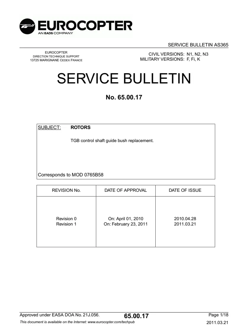
EUROCOPTER N1, N2, N3CIVIL VERSIONS:DIRECTION TECHNIQUE SUPPORT F , Fi, KMILITARY VERSIONS:13725 MARIGNANE CEDEX FRANCE
SERVICE BULLETIN No. 65.00.17 ROTORSSUBJECT:
TGB control shaft guide bush replacement.
Corresponds to MOD 0765B58 DATE OF ISSUEDATE OF APPROVALREVISION No.
2010.04.28 2011.03.21 On: April 01, 2010 On: February 23, 2011 Revision 0 Revision 1 Page 1/1865.00.17Approved under EASA DOA No. 21J.056.
2011.03.21This document is available on the Internet: www.eurocopter.com/techpub SERVICE BULLETIN AS365
1. PLANNING INFORMATION
1.A. EFFECTIVITY
1.A.1. Helicopters/installed equipment AS 365 type helicopters with TGB pre-MOD 0765B58.
Helicopter post-MOD 0765B56 on TGB are not affected by this Service Bulletin.
1.A.2. Non-installed equipment
- TGB P/N 365A33-6005-XX, equipped with:
Guide bush P/N 365A33-6188-20..
. Guide bush P/N 365A33-6189-20 or 365A33-6189-21.
1.B. ASSOCIATED REQUIREMENTS Not applicable.
1.C. REASON The purpose of this Service Bulletin Revision 0 was to improve control of the functional play between control shaft and TGB wheel in order to limit the friction loads on the control bearing.
The purpose of this Service Bulletin Revision 1 is to:
- add a figure showing seals positioning (Figure 4),
- modify the seals quantity reference AS3209-011 (addition of a seal).
Revision 1 of this Service Bulletin does not question compliance with Revision 0.
1.D. DESCRIPTION During landing, a pilot felt a loss of tail rotor control efficiency.
Further to this incident, EUROCOPTER published Alert Service Bulletin 05.00.54 (AD 2009-0247) and designed various modifications, notably 0765B58.
This modification consists of replacing both guide bushes (which ensure translation guidance of the TGB control shaft) by 2 TORLON guide bushes.This new material provides a better control of the thermal expansion coefficient.
The bush dimensions remain unchanged.
Therefore, EUROCOPTER recommends compliance with this Service Bulletin.
1.E. COMPLIANCE
1.E.1. Compliance at the works
1.E.1.a. On helicopters Not applicable.
Page 2/1865.00.17Approved under EASA DOA No. 21J.056.
2011.03.21 SERVICE BULLETIN AS365
1.E.1.b. On non-installed equipment Not applicable.
1.E.2. Compliance in service
1.E.2.a. On Helicopters/installed equipment
- EUROCOPTER recommends compliance with this Service Bulletin.
- The works must be performed by the Operator on installed equipment. Comply with Paragraph 2.B. of this Service Bulletin within 600 flying hours or at the latest within one year as from the date of issue of this Service Bulletin.
1.E.2.b. On non-installed equipment
- The works must be performed by the Operator on non-installed equipment.
- Modify stocks of TGBs as per Paragraph 2.B, before installation on helicopter or within one year maximum as from the date of issue of this Service Bulletin.
1.F. APPROVAL
1.F.1. Approval of modifications The information or instructions relating to modification 0765B58 were approved on November 16, 2009 for helicopters of civil versions subject to an Airworthiness Certificate.
1.F.2. Approval of the Service Bulletin The technical information contained in this Service Bulletin Revision 0 was approved on April 01, 2010 under the authority of EASA Design Organization Approval No. 21J.056 for helicopters of civil versions subject to an Airworthiness Certificate.
The technical information contained in this Service Bulletin Revision 0 was approved on April 01, 2010 by EUROCOPTER's Airworthiness Department for helicopters of military versions.
The technical information contained in this Service Bulletin Revision 1 was approved on February 23, 2011 under the authority of EASA Design Organization Approval No. 21J.056 for helicopters of civil versions subject to an Airworthiness Certificate.
The technical information contained in this Service Bulletin Revision 1 was approved on February 23, 2011 by EUROCOPTER's Airworthiness Department for helicopters of military versions.
The technical information contained in this Service Bulletin Revision 1 was approved on February 23, 2011 under the prerogatives of the recognition of design capability FRA21J-002-DGA for French Government helicopters.
1.G. MANPOWER
1.G.1.Qualification For compliance with this Service Bulletin Eurocopter recommends the following personnel qualifications:
Qualification: 1 Mechanical Technician.
Page 3/1865.00.17Approved under EASA DOA No. 21J.056.
2011.03.21 SERVICE BULLETIN AS365
1.G.2.Time for the operations Time for the operations is indicated for reference, for a standard configuration.
Time for the operations: 4 hours approximately.
1.G.3.Estimated helicopter grounding time
1.5 day.
1.H. WEIGHT AND BALANCE
1.H.1. Weight Not applicable.
1.H.2. Moment Not applicable.
1.I. EFFECT ON ELECTRICAL LOADS Not applicable.
1.J. SOFTWARE MODIFICATION EMBODIMENT RECORD Not applicable.
1.K. REFERENCES ROUTINE MAINTENANCE – TGB oil drainage and refilling.MET : 12.00.00.308 :
HYDRAULIC POWER SYSTEMS - General instructions.MET : 29.00.00.301 :
TRH 365A33-0030 - Tail rotor assy- Removal/Installation.MET : 64.21.00.402 :
TRH 365A33-0040 - Tail rotor assy- Removal/Installation.MET : 64.21.01.402 :
QUIET FENESTRON - Tail rotor hub - Removal/Installation.MET : 64.21.02.402 :
ROTOR CONTROLS - General instructions.MET : 67.00.00.301 :
TAIL ROTOR CONTROLS - Inspection of controls.MET : 67.21.00.601 :
SERVOCONTROLS - Removal/Installation of dual body tail rotor servocontrol.MET : 67.30.21.401 :
TAIL ROTOR GEARBOX - Removal/Installation of control rod assembly.MRR : 65.21.00.701 :
SEALING COMPOUNDS USED IN STRUCTURAL REPAIRS OR ON TRANSMISSION ASSEMBLIES - Sealing compound PR 1436GS NA (for spray application).
MTC : 20.05.01.221 :
SAFETYING AND LOCKING ASSEMBLIES - Safetying with lockwire.MTC : 20.02.06.402 :
SAFETYING AND LOCKING ASSEMBLIES - Safetying with lockplates.MTC : 20.02.06.403 :
TECHNICAL INSTRUCTIONS - Instructions applicable when working on an aircraft electrical circuit or when energizing aircraft power generating systems on ground.
MTC : 20.07.03.406 :
TECHNICAL INSTRUCTIONS - General principles applicable for visual cleanliness, appearance checks on an aircraft after an inspection or repair.
MTC : 20.07.03.408 :
Page 4/1865.00.17Approved under EASA DOA No. 21J.056.
2011.03.21 SERVICE BULLETIN AS365
1.L. OTHER DOCUMENTS AFFECTED
1.L.1. Documents already updated Not applicable.
1.L.2. Documents to be updated This Service Bulletin will give rise to amendment of the following documents by Eurocopter:
Illustrated Parts Catalog (IPC): Chapters 65.21.10 and 65.21.11.
1.M. TOOLING AFFECTED Not applicable.
1.N. INTERCHANGEABILITY OR MIXABILITY OF PARTS
1.N.1. Interchangeability New guide bushes P/N 365A33-6222-20 and 365A33-6223-20 are physically interchangeable with former guide bushes P/N 365A33-6188-20, 365A33-6189-20 and 365A33-6189-21.
1.N.2. Mixability Mixing between new guide bushes P/N (365A33-6222-20, 365A33-6223-20) (black color) and former guide bushes (P/N 365A33-6188-20, 365A33-6189-20 and 365A33-6189-21) (white color) is prohibited.
Page 5/1865.00.17Approved under EASA DOA No. 21J.056.
2011.03.21 SERVICE BULLETIN AS365
2. ACCOMPLISHMENT INSTRUCTIONS
2.A. GENERAL
2.A.1. General instructions
- Apply sealant as per MTC Work Card 20.05.01.221.
- Carry out safetying with lockwire as per MTC Work Card 20.02.06.402.
- Carry out safetying with lockplates as per MTC Work Card 20.02.06.403.
2.A.2. Special safety instructions
- Refer to general principles applicable for visual cleanliness, appearance checks on an aircraft after an inspection or repair as per MTC Work Card 20.07.03.408.
2.A.3. Document checks Not applicable.
2.B. OPERATIONAL PROCEDURE
2.B.1. Preliminary steps
- Install suitable access means.
- Disconnect all electrical power supplies as per MTC Work Card 20.07.03.406.
2.B.2. Procedure NOTE 1 The control rod assembly guide bush replacement procedure is performed without removing the TGB.
2.B.2.a. Removing TGB control rod/shaft assembly
CAUTION
BEFORE ANY INTERVENTION ON TRH ASSEMBLY, LOCK THE TRANSMISSION WITH THE ROTOR BRAKE.
- Remove tail servocontrol as per MET Work Card 67.30.21.401.
- Drain TGB as per MET Work Card 12.00.00.308.
As per Figure 1:
- Remove TRH fairing (q) after loosening bolts (r) (DETAIL A or B depending on TRH type).
NOTE 2 For aircraft equipped with quiet fenestron, bolts (r) must mandatorily be loosened at least 2 mm to allow fairing removal.
- Mark position of central plate (s) with respect to control spider (t) by a reference line.
Page 6/1865.00.17Approved under EASA DOA No. 21J.056.
2011.03.21 SERVICE BULLETIN AS365
- Unsafety nut (x).
- Position tooling (W) on nut (x) and lock control rod (b) with spanner secured on hexagon at shaft end.
- Loosen and remove nut (x), retain it.
- Remove and scrap lockwasher (z1) (pre-MOD 0765B20) or tabwasher (z2) (post-MOD 0765B20) (depending on TRH type).
- Retain washer (aa1) (pre-MOD 0765B20) or (aa2) (post-MOD 0765B20) (depending on TRH type).
- Unsafety and remove attachment bolts (u) from central plate (s) on control spider (t) and washers (v), retain them.
- Position tooling (Y) and screw in M8 bolts of tooling (Y) and by means of a mallet, gently tap at tooling center (Y) to release control shaft (b).
- Loosen and remove M8 bolts and place them on tooling (Y).
- Remove central plate (s).
- Depending on configuration (TRH post-MOD 0764B19 and pre-MOD 0764B24 ), separate and remove shim (ac) located between central plate and control spider (DETAIL C).
NOTE 3 In case of replacement of central plate (s), check interchangeability dimension as per MRR Work Card
67.21.00.701.
As per Figures 2 and 4 :
- Remove sealing bead from around cover (e) as well as from nuts (f) by means of Plexiglass scraper.
- Remove nuts (f) and washers (g).
- Remove 3 plastic plugs from cover (e).
- Remove cover (e) by means of 3 M6 bolts of suitable length (greater than cover thickness).
- Replace seals (h) and (j) from casing (ad) as required..
- Remove control rod/shaft assembly (b,c).
- Replace seals (k) and (m).
2.B.2.b.Replacing guide bushes As per Figures 2 and 3:
- On control rod (b), remove guide bush (n) and scrap it.
- As replacement for guide bush (n) install guide bush (1).
- Inside TGB on control spider side, by means of a locally-manufactured tool (spatula of type ICO
97.42.00.01.030), remove guide bush (p) and scrap it.
NOTE 4 Take care not to damage guide bush fitting groove.
- As replacement for guide bush (p) install guide bush (2).
2.B.2.c. Installing TGB control rod/shaft assembly NOTE 5 If seals (h, j, k or m) were damaged (tear, cut, crushing, etc.) , replace by new seals (3, 4, 5, 6). (See MRR Work Card 65.21.00.701).
As per Figures 1 to 4 Page 7/1865.00.17Approved under EASA DOA No. 21J.056.
2011.03.21 SERVICE BULLETIN AS365
- Thoroughly lubricate bearing with TGB oil:
Hold control rod/shaft assembly upright, rod (b) up..
. Pour oil through hole (a) and turn control rod (b) (Figure 3 DETAILS B and C).
- Wipe control rod/shaft assembly and guide bush (1).
- Fit seal (k) or seal (5) on control shaft (b) (Figure 2 DETAIL A).
- Fit seal (m) or seal (6) in recess.
- Install control rod/shaft assembly (b, c) in TGB.
- Fit O-rings (h) or (4) and (j) or (3) coated with TGB oil and place them in recess on casing (ad).
- Install cover (e).
- Fit washers (g) and nuts (f).
- Tighten nuts (f) to torque prescribed as per MRR Work Card 65.21.00.701.
- Produce sealing bead (11) around cover (e) and on nuts (f).
- Install tail servocontrol as per MET Work Card 67.30.21.401.
Aircraft equipped with 11-blade TRH:
Test yaw control travel as per MET Work Card 67.21.00.601.
CAUTION EXCEPT FOR 10-BLADE TRH, YAW CONTROL MUST
MANDATORILY BE MANEUVERED AFTER REMOVAL
OF INTERMEDIATE PLATE AS PER MET WORK CARDS
64.21.00.402 OR 64.21.01.402 OR REMOVAL OF LINK
LOCATED UPSTREAM OF REAR YAW BELLCRANK AS PER MET WORK CARD 67.00.00.301.
Aircraft equipped with 10-blade TRH:
Servocontrol travel tests will be performed on full completion of reinstallation (TGB/servocontrol/TRH) as per Paragraph 2.B.3.
As per Figure 1
- If removed (as per TRH), fit and bond with LOCTITE adhesive (14) install shim (9) (Figure 1 DETAIL C).
- Relocate central plate (s) with respect to control spider (t) by reference to line made during removal (paint, felt tip pen, etc.).
- Lubricate (with TGB oil) bolts (u), washers (v) (washer chamfers on bolt head side).
- Fit washers (v) and bolts (u) on control spider (t).
- Tighten attachment bolts (u) from central plate (s) on control spider (t) to torque prescribed as per MET Work Card 64.21.00.402 or MET Work Card 64.21.01.402 or MET Work Card 64.21.02.402.
- Safety bolts (u) by two's with lockwire (10).
- Fit plain washer (aa1) (TRH pre-MOD 0765B20) or spigot washer (aa2) (TRH post-MOD 0765B20) (DETAIL A).
- Fit lockwasher (7) (TRH pre-MOD 0765B20) or tabwasher (8) (TRH post-MOD 0765B20).
- Fit nut (x) on control rod (b).
- Position tooling (W) on nut (x).
- Lock control rod (b) with spanner secured on hexagon at shaft end and tighten to torque prescribed as per MET Work Card 64.21.00.402 or MET Work Card 64.21.01.402 or MET Work Card 64.21.02.402 with tooling (W).
NOTE 6 As required, adjust position of nut (x) to prevent any lug or tab of lockwasher (7) or tabwasher (8) from facing a nut corner, while maintaining specified tightening torque tolerance.
Page 8/1865.00.17Approved under EASA DOA No. 21J.056.
2011.03.21 SERVICE BULLETIN AS365
- Remove tooling (W).
- Safety by bending tabs of lockwasher (7) (TRH pre-MOD 0765B20) or tabwasher (8) (TRH post-MOD 0765B20) on nut (x).
- Degrease, on hub body (ab), anchorage groove of TRH fairing retaining springs (q) by means of cloth soaked with solvent (white spirit) (12) (depending on TRH type) (Figure 1 DETAIL A).
- Install TRH fairing (q) aligning red paint marks, bolts (r).
NOTE 7 Depending on TRH type, bolts (r) will be mounted with LOCTITE (13) (Figure 1 DETAIL B).
- Tighten bolts (r) to torque prescribed as per MET Work Card 64.21.00.402 or MET Work Card 64.21.01.402 or MET Work Card 64.21.02.402.
- Fill TGB with oil and top up to max. level as per MET Work Card 12.00.00.308 (MET).
- Release rotor brake.
2.B.3. Tests Aircraft equipped with 10-blade TRH:
- Reconnect all electrical power supplies as per MTC Work Card 20.07.03.406.
- Carry out operating test as per MET Work Card 67.21.00.601.
- Actuate yaw pedals and check free travel of yaw control.
- Shut down electrical power supply.
Aircraft equipped with 11-blade TRH:
- Not applicable.
2.B.4. Final steps
- Remove the access means.
2.B.5. Ground run/flight test Carry out a ground run-up of at least 5 minutes and check for any oil seepage at TGB.
Carry out checks after operations on flying controls as per Task No. 5 (hydraulic tests) of section 8.3 - Flight Manual (PMV).
2.C. OPERATIONAL PROCEDURE ON NON-INSTALLED EQUIPMENT
2.C.1. Stock retrofitting
- TGB stock retrofitting is recommended.
- Retrofit TGB as per Paragraph 2.B, before installation on helicopter or within one year maximum as from the date mentioned in page footer.
2.C.2. Stock replacement, stock scrapping and stock building-up Stock replacement and new stock building-up are incumbent on Operator.
Page 9/1865.00.17Approved under EASA DOA No. 21J.056.
2011.03.21 SERVICE BULLETIN AS365
2.D. IDENTIFICATION
2.D.1. Identification of modifications in the documentation
- Record embodiment of Modification 0765B58 and compliance with this Service Bulletin 65.00.17 Revision 1 in the aircraft documents.
- Record embodiment of Modification 0765B58 on equipment log card (FM) for TGB.
2.D.2. Identification of modifications on equipment Not applicable.
2.D.3. Identification of the new version Not applicable.
2.E. OPERATING AND MAINTENANCE INSTRUCTIONS
2.E.1. Operating instructions Not applicable.
2.E.2. Scheduled maintenance instructions Not applicable.
2.E.3. Unscheduled maintenance instructions Not applicable.
Page 10/1865.00.17Approved under EASA DOA No. 21J.056.
2011.03.21 SERVICE BULLETIN AS365
EUROCOPTER
AN EADS COMPANY SERVICE BULLETIN AS365
AVANT- PRE MOD 0765B20 X < aa1 AVANT-PRE a APRES- POST MOD 0765B20 MOD 0765B20 21-7 APRES- POST aa2 MOD 0765B20 Z2-8 14 - IS 424
APRES-POST MOD 0764B19 - CHLOCITE AVANT-PRE 242 MOD 0764B24 Figure 1 Approved under EASA DOA No. 21J.056. 65.00.17 Page 11/18 2011.03.21
EUROCOPTER
AN EADS COMPANY SERVICE BULLETIN AS365 6 Figure 2 Approved under EASA DOA No. 21J.056. 65.00.17 Page 12/18 2011.03.21