On this page
ADs that cite it · 1
Newest first, with the revision each names, as OpenAirDocs read it from the AD’s text: check it against the AD.
Text · 21Partly OCR
Some pages are OCR from a scan. OCR can misread letters and numbers. © Bombardier Inc. Filed by the FAA in regulations.gov docket FAA-2020-0100; AD 2020-03-21 incorporates this document by reference. Not covered by OpenAirDocs’ CC0 dedication.
Query with SQL
duckdb -csv -c "SELECT p.page, p.text_source, p.text, f.rights_holder, f.license
  FROM 'https://openairdocs.org/data/latest/service_document_file_page.parquet' p JOIN 'https://openairdocs.org/data/latest/service_document_file.parquet' f USING (file_sha256)
  WHERE p.file_sha256 = 'be58d2705462b886ac7b710709db5bcaa238fa0086a9d4e29a923a6728dbe2b2'
  ORDER BY p.page"
Prints the whole list as CSV. It reads the release’s Parquet files over HTTPS, so there’s nothing to download first. Install DuckDB to run it.
SELECT p.page, p.text_source, p.text, f.rights_holder, f.license
FROM 'https://openairdocs.org/data/latest/service_document_file_page.parquet' p JOIN 'https://openairdocs.org/data/latest/service_document_file.parquet' f USING (file_sha256)
WHERE p.file_sha256 = 'be58d2705462b886ac7b710709db5bcaa238fa0086a9d4e29a923a6728dbe2b2'
ORDER BY p.page
Run it at the DuckDB prompt, or in any tool that reads Parquet over HTTPS. More ways to query the release are on Use the data.
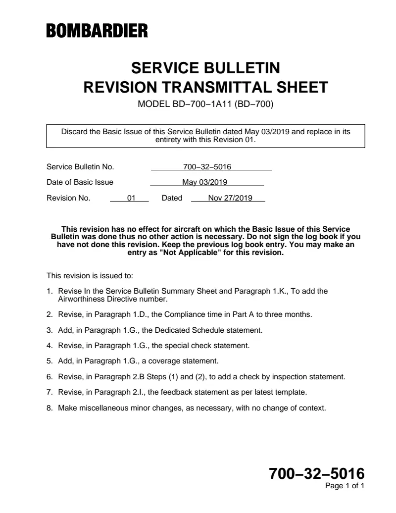
Discard the Basic Issue of this Service Bulletin dated May 03/2019 and replace in its entirety with this Revision 01.
Service Bulletin No. 700−32−5016 Date of Basic Issue May 03/2019 Revision No. 01 Dated Nov 27/2019 This revision has no effect for aircraft on which the Basic Issue of this Service Bulletin was done thus no other action is necessary. Do not sign the log book if you have not done this revision. Keep the previous log book entry. You may make an entry as "Not Applicable" for this revision.
This revision is issued to:
1. Revise In the Service Bulletin Summary Sheet and Paragraph 1.K., To add the Airworthiness Directive number.
2. Revise, in Paragraph 1.D., the Compliance time in Part A to three months.
3. Add, in Paragraph 1.G., the Dedicated Schedule statement.
4. Revise, in Paragraph 1.G., the special check statement.
5. Add, in Paragraph 1.G., a coverage statement.
6. Revise, in Paragraph 2.B Steps (1) and (2), to add a check by inspection statement.
7. Revise, in Paragraph 2.I., the feedback statement as per latest template.
8. Make miscellaneous minor changes, as necessary, with no change of context.
SERVICE BULLETIN MODEL BD−700−1A11 (BD−700) 700−32−5016 Page 1 of 1
REVISION TRANSMITTAL SHEET
SPECIAL CHECK - MAIN LANDING GEAR -
TRAILING ARM ASSEMBLY INSPECTION OF THE PAINT IN THE AXLE BORE The information below is provided for your reference. For full details, including labor and part coverage, please see corresponding paragraph contained within this bulletin.
RECOMMENDED
SPECIFIED TIME COMPLIANCE
COMPLIANCE TIME See Paragraph 1.D. for Details EFFECTIVITY: A/C Serial No. 9386, 9401, 9445 to 9997 MANPOWER: Refer to Paragraph 1.F.
CONTINUED AIRWORTHINESS (CAW)
FLEET CAMPAIGN NOYES TLMC, CH 5 AFFECTED NOYES KITS and/or PARTS NOYES
TOOLING/GSE YES NO PLANNING INFORMATION: See important information at the start of Paragraph 1. YES NO
DEDICATED SCHEDULE YES NO PREREQUISITE SERVICE BULLETINS: N/A NOTE: This Service Bulletin is subject to Airworthiness Directive TCCA−AD CF−2019−33, which will make it necessary to implement this Service Bulletin.
To place an order for parts or kits, please call Bombardier Aerospace Parts Services at:
514−855−2999 or 1−866−538−1247
SERVICE BULLETIN SUMMARY my.businessaircraft.bombardier.com MODEL BD−700−1A11 (BD−700) ATA 32−11
LANDING GEAR Basic Issue: May 03/2019 Revision 01: Nov 27/2019 700−32−5016 Page 1 of 1 This Service Bulletin is available at:
SPECIAL CHECK - MAIN LANDING GEAR -
TRAILING ARM ASSEMBLY INSPECTION OF THE PAINT IN THE AXLE BORE
1. PLANNING INFORMATION NOTES:1 . Before you do this Service Bulletin, examine all STC, STA or equivalent action changes to make sure that this Service Bulletin can be completed.
2. This Service Bulletin is covered by a dedicated schedule. Dedicated schedules are used to reserve and manage inventory due to limited availability of rotable stock, parts and/or kits. Parts are limited, therefore, advance part scheduling with our InService Implementation Team (ISIT) is recommended prior to a maintenance visit. Please contact your Regional Manager (RM), Field Service Representative (FSR) or Customer Service Representative (CSR) to schedule your aircraft as there is a limited availability. The parts will be allocated on a first come first serve basis.
For more information on dedicated schedules, refer to Service Bulletin 700−00−5002.
A. Effectivity BD−700−1A11 aircraft, Serial No. 9386, 9401, 9445 to 9997 that have a Trailing Arm assembly, Part No. 21410−107, installed.
NOTE: The instructions given in this Service Bulletin are only applicable to the systems and parts installed at the time of delivery of the aircraft or as changed by Bombardier Aerospace Service Bulletin(s).
SERVICE BULLETIN my.businessaircraft.bombardier.com MODEL BD−700−1A11 (BD−700) ATA 32−11
LANDING GEAR Refer to applicable governmental agency regulations and requirements and make sure that the work described in this Service Bulletin is performed in compliance with manufacturer’s recommendations and/or acceptable industry standards.
This document is proprietary to Bombardier Inc. and/or its affiliates and may not be reproduced or copied in any form or by any means without the prior written consent of Bombardier Inc. and/or its affiliates.
2019 Bombardier Inc. All rights reserved Learjet, Challenger, Global, are registered trademarks of Bombardier Inc. or its subsidiaries.
Basic Issue: May 03/2019 Revision 01: Nov 27/2019 700−32−5016 Page 1 of 12 This Service Bulletin is available at:
B. Reason
1. Condition:
There may be reduced adhesion of paint in the axle bore of the trailing arm assemblies, which may potentially lead to corrosion.
2. Evidence:
Four trailing arm assemblies were found with compromised paint finish and/or corrosion in the axle bores requiring removal and rework.
3. Objective/Benefit:
− Inspection will identify if the paint adhesion is affected for the listed trailing arm assemblies.
− If reduced adhesion or corrosion is found, completion of the Service Bulletin will address that.
C. Description This Service Bulletin gives instructions to:
− Inspect aircraft for installation of trailing arms listed on Table 1 in Appendix 4.
(This is Part A of the Service Bulletin).
− Inspect the affected trailing arm axle bores for paint adhesion. (This is Part B of the Service Bulletin).
− If the trailing arm is not serviceable, (that is if there were findings in Paragraph
2.C.(1)(a)), the trailing arm is repaired or replaced. The Service Bulletin provides the action to be taken.
− When a serviceable trailing arm (that is if there were no findings in Paragraph
2.C.(1)(a) is in place, the aircraft is returned to service.
− Do a second inspection on each affected trailing arm installed on the aircraft that is not marked per Paragraph 2.H. of the Service Bulletin. (i.e. ink mark beside trailing arm part number and modification plate does not show “SB700−32−041ABC”) after completing Part B of the Service Bulletin. (This is Part C of the Service Bulletin).
− Do a primer and paint removal and re−application on affected trailing arms installed on aircraft that are not marked per Paragraph 2.H. of the Service Bulletin (i.e. ink mark beside trailing arm part number and modification plate does not show “SB700−32−041ABC”) after completing Part B and C of the Service Bulletin. (This is Part D of the Service Bulletin).
D. Compliance Part A (Inspection of Part Number and Serial Number ) − Recommended to be performed in less than three months from the Revision 01 release date of this Service Bulletin.
MODEL BD−700−1A11 (BD−700) Basic Issue: May 03/2019 Revision 01: Nov 27/2019 700−32−5016 Page 2 of 12
Part B (First Inspection) − Recommended to be performed on each affected trailing arm assembly before dates listed on Table 1 in Appendix 4.
NOTE: If the Service Bulletin implemented prior to the scheduled date of Section 1 Planning Information, then there is a risk for AOG.
Part C (Second Inspection) − Recommended to be performed within 27 to 33 months after the first inspection. This second inspection is required on each affected trailing arm installed on the aircraft that is not marked per Paragraph 2.H.
of the Service Bulletin (i.e. ink mark beside trailing arm part number and modification plate does not show “SB700−32−041ABC”) after completing Part B of this Service Bulletin.
Part D (Primer and Paint Replacement) − Recommended in less than 120 months of trailing arm assembly entry into service. This task may be aligned with 120M TLMC task DETAILED INSPECTION OF THE TRAILING ARM/AXLE ASSEMBLY (Chapter 5 Task No. 32−10−00−208). This inspection is required on aircraft that are not marked per Paragraph 2.H. of the Service Bulletin (i.e. ink mark beside trailing arm part number and modification plate does not show “SB700−32−041ABC”) after completing Part B and C of this Service Bulletin.
NOTE: If it is not possible to complete all the instructions in this Service Bulletin because of the aircraft configuration, submit an SRPSA for analysis and to get an approved disposition to complete this Service Bulletin.
E. Approval The technical content of this Service Bulletin has been approved under the authority of Transport Canada Civil Aviation (TCCA) Design Approval Organization (DAO) No. DAO #93−Q−02.
NOTES: 1. The technical content of this Service Bulletin is accepted by the FAA under the Canada/USA bilateral Aviation Safety Agreement.
2. The technical content of this Service Bulletin is accepted by EASA under the Canada/EU bilateral Aviation Safety Agreement.
F. Manpower NOTES: 1. The man−hours given are to help you schedule the tasks given in this bulletin. The man−hours are for direct labor performed by an experienced crew and do not include the time for familiarization, planning, aircraft preparation in hangar such as towing and positioning of scaffolds, removal of interior furnishings, repainting, supervision and inspection.
For more information related to the manpower, refer to SB 700−00−5002.
2. This Service Bulletin may require consumable materials that have specific curing times (refer to Paragraph 3). The accumulated curing time is not included in the man−hours and should be considered for planning purposes before you schedule this Service Bulletin.
MODEL BD−700−1A11 (BD−700) Basic Issue: May 03/2019 Revision 01: Nov 27/2019 700−32−5016 Page 3 of 12
0.25 man−hours per trailing arm assembly is necessary to do PART A of this Service Bulletin.
Bombardier Aerospace does not pay for the labor to do PART A of this Service Bulletin.
3 man−hours per trailing arm assembly are necessary to do PART B and PART C of this Service Bulletin.
The labor required to do PART B and PART C of this Service Bulletin is at no cost if:
− the work is done at Bombardier Business Aviation Services (BBAS) or Authorized Service Facilities (ASF), and − this Service Bulletin is scheduled according to Paragraph 1.D.
G. Material − Cost and Availability This Service Bulletin is covered by a dedicated schedule. Dedicated schedules are used to reserve and manage inventory due to limited availability of rotable stock, parts and/or kits. Parts are limited, therefore, advance part scheduling with our InService Implementation Team (ISIT) is recommended prior to a maintenance visit. Please contact your Regional Manager (RM), Field Service Representative (FSR) or Customer Service Representative (CSR) to schedule your aircraft as there is a limited availability. The parts will be allocated on a first come first serve basis.
No kits or parts are necessary to do this special check. If corrosion is found, a replacement trailing arm, Part No. 21410−107, needs to be ordered. The exchange is Free of Charge (FOC).
If the trailing arm does not show signs of corrosion but paint bubbling or visible primer is spotted, then a repair might be necessary. The repair is covered FOC.
Smart Parts does not cover any parts ordered for this Service Bulletin at any time.
H. Tooling The equipment and tools listed below are necessary to do this Service Bulletin:
GSE REFERENCE NO. PART NO. DESCRIPTION Commercially Available − Boroscope I. Weight and Balance No change.
J. Electrical Load Data No change.
MODEL BD−700−1A11 (BD−700) Basic Issue: May 03/2019 Revision 01: Nov 27/2019 700−32−5016 Page 4 of 12
K. References − Airworthiness Directive TCCA−AD CF−2019−33.
− Global 5000 BD−700 Aircraft Maintenance Manual (AMM), Chapters 6, 24, and 32.
− SAFRAN Landing Systems, Service Bulletin 700−32−041 − SAFRAN Landing Systems, Component Maintenance Manual (CMM), Chapter 32.
− Bombardier Aerospace, Service Bulletin 700−32−5016, Appendix 1 (attached).
− Bombardier Aerospace, Service Bulletin 700−32−5016, Appendix 2 (attached).
− Bombardier Aerospace, Service Bulletin 700−32−5016, Appendix 3 − Examples of bubbling paint and corrosion.
− Bombardier Aerospace, Service Bulletin 700−32−5016, Appendix 4 − List of affected trailing arm serial numbers and due dates for first inspection.
L. Other Publications Affected None.
M. Equivalent Service Bulletin − For the Global Express and Global Express XRS BD−700−1A10 aircraft, use Service Bulletin 700−32−039.
− For the Global 5000 BD−700−1A11 aircraft, use Service Bulletin 700−1A11−32−026.
− For the Global 6000 BD−700−1A10 aircraft, use Service Bulletin 700−32−6016.
2. ACCOMPLISHMENT INSTRUCTIONS NOTES: 1. All TASKs given in the procedures that follow are from the Global 5000 BD−700−1A11 aircraft Featuring Global Vision Flight Deck, Aircraft Maintenance Manual (AMM) unless otherwise specified.
2. All references made to zones, access panels and/or doors, are from the Global 5000 BD−700−1A11 aircraft Featuring Global Vision Flight Deck, Aircraft Maintenance Manual (AMM), Chapter 6.
A. Aircraft Setup NOTE: The steps in the Aircraft Set−Up section of this Service Bulletin are recommended steps. The steps give a recommendation to get access to the work area. This recommendation is to give a safe work area and to minimize possible damage to surrounding aircraft parts. Alternative steps can be used at the operator discretion.
(1) Obey all electrical/electronic safety precautions. Refer to AMM 24−00−00−910−801.
(2) Obey the landing−gear safety precautions. Refer to AMM 32−00−00−910−801.
MODEL BD−700−1A11 (BD−700) Basic Issue: May 03/2019 Revision 01: Nov 27/2019 700−32−5016 Page 5 of 12
B. PART A − Inspection of Part Number and Serial Number NOTES: 1. If it is not possible to complete all the instructions in this Service Bulletin because of the configuration of the aircraft, submit an SRPSA for analysis and to get an approved disposition to complete this Service Bulletin.
2. The complete area of the trailing arm axle ID shall be inspected, including the central cavity around the wheel speed transducer harnesses.
(1) Inspect the RH and LH trailing arm assemblies to see if Part No. 21410−107 is installed. Part number may also be checked by inspection of aircraft records.
(2) If Part No. 21410−107 is installed, inspect the Serial No. stamped on the RH and LH trailing arm assemblies. Serial number may also be checked by inspection of aircraft records.
(3) If the serial numbers of the RH and LH trailing arm assemblies are not listed on Table 1 in Appendix 4, no further action is required. Make an entry in the aircraft log book that PART A is accomplished and the axle bore inspection is not required. Continue at to Paragraph 2.I.
(4) If the serial numbers of the RH and/or LH trailing arm assemblies are listed on Table 1 in Appendix 4, further action is required. Make an entry in the aircraft log book that PART A is accomplished and affected trailing arm(s) are installed and require inspection. Record affected serial numbers that are installed and side(s) affected (i.e. LH, RH, or both sides affected). Schedule first inspection (Part B) per compliance time stated in Paragraph 1.D. and continue to Paragraph 2.I.
C. PART B − First Inspection
(1) If trailing arms with affected Part No. and Serial No. are installed on the aircraft, remove the inboard and outboard wheel speed transducers (per AMM 32−43−53−000−801) on affected trailing arm assemblies to gain access and perform the following:
(a) Do visual and borescope inspections of the axle bores on each affected trailing arm assembly for the following. Refer to Figure A, in Appendix 3.
(i) Paint that is bubbling, loose, flaking, cracked, damaged or missing,
(ii) Visible primer and/or metallic−ceramic coating,
(iii) Signs of corrosion.
(b) If inspection findings are per paragraph 2.C.(1)(a)(iii), the corroded trailing arm assembly(s) needs to be replaced.
(i) Fill in the form at Appendix 1 for each corroded trailing arm assembly.
(ii) Send the form(s) to the Retrofit Team at retrofit.tor.sls@safrangroup.com.
MODEL BD−700−1A11 (BD−700) Basic Issue: May 03/2019 Revision 01: Nov 27/2019 700−32−5016 Page 6 of 12
(iii) Remove the corroded trailing arm assembly(s). Refer to AMM 32−11−09−000−801.
(iv) Install the new or reworked trailing arm assembly(s) on RH and LH sides where corroded trailing arm assembly(s) were removed in Paragraph 2.C.(1)(b)(iii). Refer to AMM 32−11−09−400−801.
NOTE: If received trailing arm serial numbers are listed on Table 1 in Appendix 4 then verify it has been marked per Paragraph
2.H. of this Service Bulletin, indicating that it has been repaired.
(c) If inspection findings are as per paragraph 2.C.(1)(a)(i) or (ii), fill form in Appendix 2 for each affected trailing arm assembly and send to technical.concession.tor.sls@safrangroup.com with photographs of discrepancies. Photos to show locations and severity of surface finish discrepancies. Refer to VSB SL700−32−07 for details on how to submit a concession. The completion of the concession process will correct the findings. Comply with the concession on each affected trailing arm assembly.
(d) If all affected trailing arm assemblies are serviceable (that is if there were no findings in paragraph 2.C.(1)(a)), make an entry in the aircraft log book that Part B is accomplished.
(e) Once all affected trailing arm assemblies have accomplished Paragraph
2.C.(1)(b), Paragraph 2.C.(1)(c), and Paragraph 2.C.(1)(d), as applicable, make an aircraft log entry that PART B is accomplished, send Incorporation Notice to Bombardier Business Aircraft Customer Services (BBACS), then continue at Paragraph 2.F.
D. PART C − Second Inspection NOTES: 1. If it is not possible to complete all the instructions in this Service Bulletin because of the configuration of the aircraft, submit an SRPSA for analysis and to get an approved disposition to complete this Service Bulletin.
2. The complete area of the axle ID shall be inspected, including the central cavity around the wheel speed transducer harnesses.
(1) For any affected trailing arm installed on the aircraft that are not marked per Paragraph 2.H. of the Service Bulletin (i.e. ink mark beside trailing arm part number and modification plate does not show “SB700−32−041ABC”) after completing Part B of the Service Bulletin, perform a second repeat inspection (per Paragraph 2.C.) on those units, within 27 to 33 months after the first inspection.
(2) Once all affected trailing arm assemblies have accomplished Paragraph
2.D.(1), make an entry in the aircraft log book that Part C is accomplished, send Incorporation Notice to Bombardier Business Aircraft Customer Services (BBACS), and then proceed to Paragraph 2.F.
MODEL BD−700−1A11 (BD−700) Basic Issue: May 03/2019 Revision 01: Nov 27/2019 700−32−5016 Page 7 of 12
E. PART D − Primer and Paint Replacement NOTES: 1. If it is not possible to complete all the instructions in this Service Bulletin because of the configuration of the aircraft, submit an SRPSA for analysis and to get an approved disposition to complete this Service Bulletin.
2. The complete area of the axle ID shall be inspected, including the central cavity around the wheel speed transducer harnesses.
(1) For any affected trailing arm installed on the aircraft that are not marked per Paragraph 2.H. of the Service Bulletin (i.e. ink mark beside trailing arm part number and modification plate does not show “SB700−32−041ABC”) after completing Part C of the Service Bulletin, then perform the following in less than 120 months of trailing arm assembly entry into service on those units.
This task may be aligned with 120M TLMC task DETAILED INSPECTION OF THE TRAILING ARM/AXLE ASSEMBLY (Ref. Chapter 5 Task No.
32−10−00−208).
(a) Remove the affected trailing arm assembly(s). Refer to AMM 32−11−09−000−801.
(b) Refer to paragraph 7.G. of the REPAIR section of the CMM 32−10−11 (Repair − General Repairs). Remove the paint and the primer from the inner diameter of the axle on the affected trailing arm assembly.
(c) Refer to paragraph 7.G. of the REPAIR section of the CMM 32−10−11 (Repair − General Repairs). Inspect the metallic−ceramic coating on the inner diameter of the axle on the affected trailing arm assembly. If coating is acceptable, continue to the next step, otherwise repair the metallic−ceramic coating per paragraph 7.G. of the CMM before continuing to the next step.
(d) Refer to paragraph 7.G. of the REPAIR section of the CMM 32−10−11 (Repair − General Repairs). Prepare inner diameter of the axle on the affected trailing arm assembly for primer and paint application.
(e) Refer to paragraph 7.G. of the REPAIR section of the CMM 32−10−11 (Repair − General Repairs). Apply primer and paint on the inner diameter of the axle on the affected trailing arm assembly.
(f) Refer to paragraph 7.G. of the REPAIR section of the CMM 32−10−11 (Repair − General Repairs). Apply corrosion preventive compound on the inner diameter of the axle on the affected trailing arm assembly.
(g) Install the affected trailing arm assembly(s). Refer to AMM 32−11−09−400−801.
(2) After all affected trailing arm assemblies have been reworked per Paragraph
2.E. (1), make an entry in the aircraft log book that Part D is accomplished and send Incorporation Notice to Bombardier Business Aircraft Customer Services (BBACS).
(3) Proceed to Paragraph 2.F.
MODEL BD−700−1A11 (BD−700) Basic Issue: May 03/2019 Revision 01: Nov 27/2019 700−32−5016 Page 8 of 12
F. Close−out NOTES: 1. The steps in the Close−out section of this Service Bulletin, except for the return−to−service tests, are recommended steps. The steps give a recommendation to install components removed during the Aircraft Setup. This recommendation is to make sure that the aircraft is safe and ready to return to service. Alternative steps can be used at the operator discretion.
2. The steps below in the Close−out section are per affected trailing arm assembly.
(1) Remove all tools, equipment and unwanted materials from the aircraft.
(2) Install any inboard and outboard wheel speed transducers that were removed in order to perform the Service Bulletin inspection. Refer to AMM 32−43−53−400−801.
(3) If this was the first inspection of the trailing arm assembly for this Service Bulletin, plan a second inspection (Part C of this Service Bulletin) for each affected trailing arm assembly installed on the aircraft that is not marked per Paragraph 2.H. of the Service Bulletin (i.e. ink mark beside trailing arm part number and modification plate does not show “SB700−32−041ABC”) in accordance with Paragraph 1.D., and continue to identification in accordance with Paragraph 2.G.
(4) If this was the second inspection of the trailing arm assembly for this Service Bulletin, plan a primer and paint removal and re−application (Part D of this Service Bulletin) on affected trailing arm assemblies installed on aircraft that are not marked per Paragraph 2.H. of the Service Bulletin (i.e. ink mark beside trailing arm part number and modification plate does not show “SB700−32−041ABC”) in accordance with Paragraph 1.D. and continue to identification in accordance with Paragraph 2.G.
(5) If this was the Replacement of the Paint and Primer in accordance with Paragraph 2.E., then continue to identification in accordance with Paragraph
2.H.
(6) If the trailing arm assembly was repaired by concession for this Service Bulletin, the concession will have the necessary instructions for identification in accordance with Paragraph 2.G. or 2.H., whichever applicable.
(7) This Service Bulletin is applicable to the aircraft and to be accomplished on each affected gear. The intent of the Service Bulletin is fulfilled only when all affected trailing arms have been replaced by unaffected trailing arms on the aircraft or all affected trailing arms installed on the aircraft are marked per Paragraph 2.H. of the Service Bulletin (i.e. ink mark beside trailing arm part number and modification plate shows “SB700−32−041ABC”). If intent of Service Bulletin is fulfilled, proceed to Paragraph 2.I. and make an aircraft log entry and send Incorporation Notice to Bombardier Business Aircraft Customer Services (BBACS).
MODEL BD−700−1A11 (BD−700) Basic Issue: May 03/2019 Revision 01: Nov 27/2019 700−32−5016 Page 9 of 12
G. Identification (After First or Second Inspection) NOTE: Identification by customer is only needed on units that are deemed serviceable after performing the applicable inspection. In the cases where the unit after inspection is deemed not serviceable, the replacement unit will be marked correctly at supplier facility already prior to shipment to customer.In the cases where the inspected unit is managed by concession, the unit will be marked correctly during the concession.
(1) Identify each affected unit after the first inspection is completed and the trailing arm assembly(s) is serviceable as follows.
(a) Ink mark SB700−32−041A on the trailing arm assembly near the part number. Refer to Figure B, SAFRAN Service Bulletin 700−32−041 and PCS−6000 Method 07.
(b) Ink mark SB700−32−041A in the next available space on the modification plate. Refer to Figure C, SAFRAN Service Bulletin 700−32−041 and PCS−6000 Method 07.
(2) Add to the identification of each affected unit after the second inspection is completed and the trailing arm assembly(s) is serviceable as follows.
(a) Ink mark SB700−32−041AB on the trailing arm assembly near the part number. Refer to Figure B, SAFRAN Service Bulletin 700−32−041 and PCS−6000 Method 07.
(b) Ink mark SB700−32−041AB in the next available space on the modification plate. Refer to Figure C, SAFRAN Service Bulletin 700−32−041 and PCS−6000 Method 07.
H. Identification (After re−applying the primer and paint on the trailing arm axle’s inner diameter per Part D of this Service Bulletin)
(1) Add to the identification of each affected unit after axle inner diameter primer and paint is reapplied per paragraph 2.E. and the trailing arm assembly(s) is serviceable as follows.
(a) Ink mark SB700−32−041ABC on the trailing arm assembly near the part number. Refer to Figure B, SAFRAN Service Bulletin 700−32−041 and PCS−6000 Method 07.
(b) Ink mark SB700−32−041ABC in the next available space on the modification plate. Refer to Figure C, SAFRAN Service Bulletin 700−32−041 and PCS−6000 Method 07.
NOTE: Identification of all affected trailing arm assemblies installed on aircraft per 2.H.(1) indicates completion of Service Bulletin and intent of Service Bulletin met. Proceed to Paragraph 2.I. and make an aircraft log entry and send an Incorporation Notice to Bombardier Business Aircraft Customer Services (BBACS).
MODEL BD−700−1A11 (BD−700) Basic Issue: May 03/2019 Revision 01: Nov 27/2019 700−32−5016 Page 10 of 12